
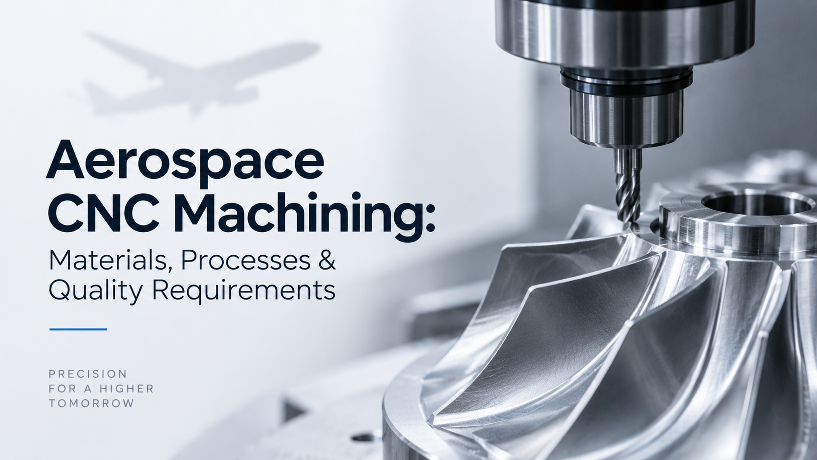
Aerospace CNC machining is the controlled manufacture of precision aircraft, spacecraft, UAV, propulsion, structural, and support components using computer-controlled milling, turning, drilling, EDM, and related processes.
What separates aerospace machining from ordinary CNC work is not simply a tighter tolerance.
Aerospace components may combine difficult materials, thin walls, complex geometry, critical datum relationships, demanding surface requirements, controlled special processes, detailed inspection, material traceability, and extensive manufacturing records.
For this reason, successful aerospace machining depends on the complete manufacturing process — from material identification and machining strategy to inspection and documentation — rather than the CNC machine alone.
What Is Aerospace CNC Machining?
Aerospace CNC machining uses computer-controlled machining processes to manufacture components according to tightly controlled engineering, material, inspection, and documentation requirements for aviation, space, and related applications.
Typical components include:
- Structural brackets
- Housings
- Fittings
- Shafts
- Bushings
- Actuator components
- Manifolds
- Sensor housings
- Engine-related components
- UAV structures
- Satellite hardware
- Ground-support tooling
- Test fixtures
Not every part described as “aerospace” carries the same requirements.
A flight-critical component and a development fixture may use similar CNC machines but have very different requirements for material certification, inspection, traceability, special-process approval, and quality-system certification.
That distinction should be established before quoting or manufacturing begins.
Why Is CNC Machining Used in Aerospace Manufacturing?
CNC machining is well suited to aerospace manufacturing because it combines geometric flexibility with repeatable material removal.
Complex Geometry
Aircraft and spacecraft components frequently contain:
- Deep pockets
- Thin ribs
- Compound angles
- Multiple datum surfaces
- Closely controlled hole patterns
- Curved surfaces
- Internal bores
- Sealing faces
CNC machining allows these features to be produced directly from a digital model and controlled program.
High-Performance Materials
Aerospace engineering uses materials selected primarily for performance rather than ease of manufacturing.
CNC processes can machine materials such as:
- 2024 aluminum
- 6061 aluminum
- 7075 aluminum
- Titanium alloys
- Stainless steels
- Nickel-based superalloys
However, machining strategy changes substantially between these material families.
Prototype-to-Production Flexibility
Unlike manufacturing methods that require dedicated dies or molds, CNC machining can be practical for:
- Development parts
- Engineering prototypes
- Low-volume production
- Replacement components
- High-mix manufacturing
- Production batches
This flexibility is especially useful during aerospace product development, where designs may change between iterations.
Common Aerospace CNC Machining Processes
Different aerospace geometries require different machining strategies.
3-Axis CNC Milling
Three-axis milling moves the cutting tool along the X, Y, and Z axes.
It is suitable for many:
- Plates
- Brackets
- Simple housings
- Pockets
- Mounting components
- Fixtures
3-axis machines remain highly capable when the component can be accessed from a limited number of orientations.
Their main limitation is that complex multi-face parts may require repeated repositioning.
Every additional setup introduces another opportunity for datum-transfer error.
4-Axis CNC Machining
Four-axis machining adds rotational movement.
This allows the manufacturer to machine several sides of a component without repeatedly removing and manually repositioning it.
Typical applications include:
- Cylindrical components
- Multi-side hole patterns
- Rotary features
- Housings
- Parts requiring indexed machining
Reducing manual repositioning can simplify process planning and improve control of relationships between features.
5-Axis CNC Machining
Five-axis CNC machining allows the cutting tool or workpiece to move simultaneously or positionally across five axes.
This is particularly valuable for aerospace components with complex geometry.
Typical applications include:
- Impellers
- Turbomachinery components
- Structural brackets
- Complex housings
- Deep cavities
- Compound-angle holes
- Curved surfaces
The major advantage is not simply that “five axes are more accurate.”
The real advantage is access.
More features can often be machined in one setup, reducing repositioning and helping preserve geometric relationships between datums, bores, holes, and surfaces.
NIST has documented the use of advanced 5-axis machining in aerospace manufacturing for complex components, along with process optimization, probing, and in-machine measurement strategies.
Why Fewer Setups Matter
Consider a housing requiring five precision holes on different faces.
If each face requires a separate setup, every repositioning introduces variables involving:
- Fixture location
- Datum transfer
- Clamping
- Machine alignment
- Operator setup
A suitable 5-axis strategy can machine more of these features from a common reference condition.
That does not eliminate process error, but it can reduce one major source of variation.
CNC Turning
Turning remains important for aerospace components with rotational geometry.
Examples include:
- Shafts
- Pins
- Bushings
- Sleeves
- Fittings
- Connectors
- Cylindrical valve components
Critical requirements may include:
- Diameter
- Roundness
- Runout
- Concentricity
- Cylindricity
- Surface finish
- Thread geometry
Mill-Turn Machining
Mill-turn machines combine turning and milling functions.
A component can therefore have:
- Diameters turned
- Flats milled
- Cross holes drilled
- Slots machined
- Threads produced
without moving through multiple independent machines.
As with 5-axis milling, the key advantage is often reducing handling and maintaining relationships between features.
EDM in Aerospace Machining
Electrical discharge machining removes material through controlled electrical discharge rather than conventional cutting.
Wire EDM and sinker EDM can be useful for:
- Hard materials
- Fine slots
- Difficult internal geometry
- Features requiring low mechanical cutting force
- Shapes that are difficult to reach with rotating cutting tools
EDM should not be considered the default process for every hard aerospace alloy. It is selected when geometry, material condition, tolerance, or process requirements justify it.
Aerospace Materials Used in CNC Machining
Material selection is one of the defining characteristics of aerospace manufacturing.
| Material | Main Advantages | Main Machining Challenges | Typical Applications |
|---|---|---|---|
| Aluminum | Lightweight, machinable, good strength-to-weight ratio | Distortion, burrs, thin-wall movement | Structures, housings, brackets |
| Titanium | High strength-to-weight ratio, corrosion resistance | Heat concentration, tool wear, low thermal conductivity | Structural and engine-related components |
| Stainless steel | Strength, corrosion resistance, durability | Work hardening, cutting forces | Fittings, shafts, mechanical components |
| Nickel superalloys | High-temperature strength | Severe tool wear, heat, work hardening | Engine and hot-section applications |
Aerospace Aluminum Machining
Aluminum remains one of the most important aerospace machining materials because of its low density and useful strength-to-weight ratio.
2024 Aluminum
2024 is associated with aerospace structural applications where strength and fatigue performance are important.
Machining considerations include:
- Burr formation
- Thin-wall stability
- Surface quality
- Residual stresses
- Corrosion-protection requirements
6061 Aluminum
6061 offers good machinability and is widely used for housings, brackets, fixtures, UAV components, and general aerospace-related hardware.
It is also compatible with common secondary processes such as anodizing.
7075 Aluminum
7075 provides significantly higher strength than many general-purpose aluminum alloys.
It is widely associated with aerospace structures and high-strength mechanical components.
However, strong material does not automatically mean difficult cutting in the same way as titanium or nickel superalloys.
For aluminum aerospace parts, one of the bigger manufacturing challenges can instead be distortion after removing large amounts of material.
Why Thin-Wall Aluminum Parts Distort
Aerospace structural components are frequently machined from relatively large billets or plates and reduced to thin ribs and walls.
Large amounts of material may be removed to minimize final component weight.
This changes the balance of stresses within the material.
Distortion can be influenced by:
- Residual stress in the raw material
- Material condition
- Cutting forces
- Heat
- Clamping
- Material-removal sequence
- Wall thickness
- Geometry
- Toolpath
A component may measure correctly while heavily clamped and move after it is released.
For this reason, inspection strategy matters just as much as the machining program.
How Aerospace Manufacturers Control Distortion
There is no universal method, but common process strategies include:
Balanced Material Removal
Material may be removed strategically rather than machining one area completely before another.
Roughing and Finishing Stages
A component may first be rough machined, leaving finishing allowance.
Final dimensions are then produced after the major bulk of material has been removed.
Controlled Workholding
Fixtures need enough rigidity to resist cutting loads without unnecessarily deforming the component.
More clamping force is not always better.
Thin components can be distorted by the fixture itself.
Toolpath Planning
Cutting strategy can influence:
- Cutting force
- Heat generation
- Tool engagement
- Wall deflection
Inspection After Unclamping
Where deformation risk is significant, dimensional verification should represent the part in the condition defined by the drawing or inspection specification.
Titanium Aerospace Machining
Titanium alloys are important in aerospace because they combine:
- High strength
- Low density relative to steels
- Corrosion resistance
- Useful high-temperature properties
Ti-6Al-4V is one of the best-known aerospace titanium alloys.
Its advantages in service create significant machining challenges.
Why Is Titanium Difficult to Machine?
Titanium is difficult to machine largely because heat does not move away from the cutting zone efficiently.
NIST research on Ti-6Al-4V identifies low thermal conductivity as a key reason machining produces high temperatures at the tool-chip interface. Titanium also exhibits chemical reactivity and other material characteristics that complicate cutting.
This creates several problems.
Cutting Heat
A greater proportion of the machining heat remains concentrated around the cutting edge.
Tool Wear
High local temperature and tool-material interaction can accelerate wear.
As the tool wears, the manufacturer may begin to lose control of:
- Dimensions
- Surface finish
- Burr condition
- Process stability
Tool Deflection and Cutting Forces
Titanium machining requires rigid workholding, suitable cutting tools, and stable engagement.
Coolant Strategy
Coolant delivery becomes especially important when controlling heat at the cutting zone and supporting chip evacuation.
For aerospace titanium machining, selecting a cutting speed from a generic online chart is not enough.
Parameters should reflect the actual combination of:
- Alloy
- Tool material
- Tool geometry
- Machine rigidity
- Engagement
- Coolant
- Feature geometry
Machining Nickel-Based Superalloys
Nickel-based superalloys such as Inconel are used where components must retain strength at elevated temperatures.
That makes them attractive for demanding aerospace propulsion applications.
It also makes them difficult to machine.
Research published by SAE notes that Inconel 718 combines elevated-temperature strength with relatively low thermal conductivity, contributing to high cutting force, high machining temperature, and multiple tool-wear mechanisms.
Typical challenges include:
- Rapid tool wear
- Heat concentration
- Work hardening
- High cutting forces
- Surface-integrity concerns
- Reduced productivity
Stable machining is particularly important.
If the tool repeatedly rubs rather than cutting efficiently, the surface can work harden and make subsequent machining even more difficult.
Aerospace Machining Tolerances
There is no universal aerospace CNC tolerance.
Statements such as “all aerospace parts require ±0.005 mm” are misleading.
Tolerance is determined by:
- Component function
- Part size
- Assembly
- Material
- Feature geometry
- Datum structure
- Drawing requirements
- Manufacturing process
- Inspection capability
A structural pocket may have a relatively open tolerance while the same component contains a precision bearing bore with a much tighter requirement.
Common Critical Features
Typical high-control features include:
- Bearing bores
- Pin holes
- Hole patterns
- Sealing faces
- Mating surfaces
- Coaxial diameters
- Datum surfaces
- Interface locations
Aerospace precision should therefore be discussed feature by feature, not by attaching one impressive tolerance to the entire part.
Why GD&T Matters in Aerospace Machining
Aerospace components often depend on relationships between features rather than only individual dimensions.
Geometric Dimensioning and Tolerancing can control characteristics such as:
- Position
- Flatness
- Perpendicularity
- Parallelism
- Profile
- Runout
- Concentric relationships
Consider two holes that are individually the correct diameter.
The part can still fail if their positions relative to the datum structure are incorrect.
Good aerospace inspection must therefore verify both size and geometry.
Surface Finish and Surface Integrity
Dimensional accuracy alone does not guarantee an acceptable aerospace component.
Surface condition can influence:
- Assembly
- Sealing
- Wear
- Friction
- Fatigue
- Coating performance
Relevant requirements may include:
- Surface roughness
- Burr control
- Tool marks
- Edge condition
- Scratches
- Thermal damage
- Surface contamination
The required surface condition varies significantly by feature.
A cosmetic cover, bearing surface, sealing face, and fatigue-sensitive structural area should not automatically receive the same finish specification.
Quality Requirements in Aerospace CNC Machining
Aerospace quality should be treated as a manufacturing system rather than an inspection department at the end of production.
Important elements can include:
- Drawing revision control
- Material identification
- Process planning
- Tool control
- Calibration
- Inspection planning
- Nonconformance control
- Change management
- Supplier control
- Documentation
- Traceability
- First Article Inspection
The exact requirements come from the customer, drawing, purchase order, regulatory environment, and applicable quality standards.
AS9100 and Aerospace Machining
AS9100D is a quality management system standard for aviation, space, and defense organizations.
It incorporates ISO 9001:2015 requirements while adding aerospace-specific requirements. SAE explicitly describes those additional aerospace requirements as complementary to customer and statutory or regulatory requirements rather than replacements for them.
AS9100 Is Not a Machining Tolerance Standard
AS9100 does not tell a machinist that a particular bore must be ±0.005 mm.
Instead, it addresses the management systems needed to consistently satisfy defined requirements.
The IAQG describes 9100 as a quality-management framework designed for organizations throughout the aviation, space, and defense supply chain.
Is AS9100 Certification Required for Every Aerospace Part?
No.
Whether certification is required depends on:
- Customer requirements
- Contract terms
- Program
- Supply-chain level
- Part classification
Many aerospace OEMs and Tier suppliers require AS9100 certification from production suppliers, particularly for controlled aerospace hardware.
But an aerospace development fixture or non-flight prototype does not automatically create the same contractual requirement.
The RFQ and purchase-order quality clauses should determine what applies.
AS9100D and the Upcoming IA9100
As of September 2026, SAE still lists AS9100D, revised in 2016, as the verified current SAE revision.
The IAQG is developing its successor under the new designation IA9100, with publication expected later in 2026. It should therefore not yet be described as an already-issued replacement.
What Is AS9102 First Article Inspection?
First Article Inspection is a structured verification that the planned production process can produce a part that meets the defined engineering requirements.
SAE AS9102 establishes documentation requirements for aerospace First Article Inspection. The current revision is AS9102C, published in June 2023.
FAI should not be reduced to:
“Measure one finished part.”
A meaningful first article package may involve evidence relating to:
- Drawing characteristics
- Dimensions
- GD&T
- Material requirements
- Processes
- Notes
- Inspection results
- Required documentation
Ballooned Drawings
A common FAI workflow identifies or “balloons” individual drawing requirements so that each requirement can be linked to corresponding inspection or verification evidence.
This improves completeness.
Instead of asking:
“Did we measure the part?”
the process asks:
“Have we accounted for every applicable engineering requirement?”
Material Traceability in Aerospace Machining
Material identity can be as important as dimensional conformity.
A part manufactured from the wrong alloy may measure perfectly and still be unusable.
Traceability systems may link a finished part or production lot to:
- Material grade
- Material condition
- Heat number
- Lot number
- Mill certificate
- Purchase records
- Internal job records
The level of required traceability depends on contract and customer requirements.
Why Traceability Matters
Suppose a material problem is discovered after production.
Without traceability, the manufacturer may not know which parts came from the affected raw-material batch.
With an effective traceability system, potentially affected production can be identified much more precisely.
Inspection Methods for Aerospace CNC Parts
Inspection equipment should be selected according to the characteristic being measured.
Common methods include:
Micrometers
Useful for controlled diameters and thickness measurements.
Bore Gauges
Appropriate for precision internal diameters when properly set and controlled.
Height Gauges
Useful for many dimensional checks referenced from a surface plate.
CMM Inspection
Coordinate Measuring Machines can measure complex three-dimensional geometry and evaluate GD&T requirements.
Optical Measurement
Useful for certain small, delicate, profile, or non-contact measurement tasks.
Surface Roughness Measurement
Used where surface texture is functionally specified.
CMM Inspection in Aerospace Manufacturing
CMM inspection is especially valuable for components containing:
- Complex datum systems
- True-position requirements
- Profiles
- Multi-face features
- Compound geometry
A typical CMM workflow involves:
- Establishing the required datum alignment
- Measuring defined features
- Evaluating dimensional and geometric requirements
- Producing an inspection report
However, a CMM is not automatically the best instrument for every measurement.
Metrology should be selected based on:
- Feature geometry
- Tolerance
- Accessibility
- Measurement uncertainty
- Inspection method
Good inspection planning starts during process planning, not after parts have already been machined.
Special Processes and Secondary Finishing
Aerospace machined parts may require secondary processes such as:
- Anodizing
- Chemical conversion coating
- Passivation
- Plating
- Heat treatment
- Grinding
- Shot peening
- Welding
- Non-destructive testing
- Painting
Some aerospace contracts require these operations to be performed by specifically approved or accredited suppliers.
What About Nadcap?
Nadcap is an industry-managed accreditation program covering critical aerospace processes.
Performance Review Institute lists accreditation areas including:
- Heat treating
- Chemical processing
- Non-destructive testing
- Welding
- Coatings
- Surface enhancement
and other critical process categories.
But Nadcap should not be written onto every aerospace RFQ automatically.
The customer specification and approved-supplier requirements determine whether it applies.
Prototype vs Production Aerospace Machining
Aerospace prototypes and production parts can require very different manufacturing priorities.
| Area | Prototype | Production |
|---|---|---|
| Primary goal | Validate design | Maintain repeatability |
| Quantity | Usually low | Repeated batches |
| Process optimization | Flexible | Highly controlled |
| Tooling | May be simplified | Optimized for consistency |
| Documentation | Project-dependent | Often more structured |
| Inspection | Design validation | Repeatable process verification |
| Cost focus | Speed and learning | Process capability and stability |
Prototype Stage
The emphasis may be on:
- Design verification
- Fit
- Function
- DFM feedback
- Fast revision
Production Stage
The focus shifts toward:
- Repeatable workholding
- Stable tooling
- Tool-life management
- Inspection efficiency
- Traceability
- Lot consistency
- Controlled revisions
A manufacturing process that successfully produces three prototypes is not automatically production-ready for hundreds of parts.
Common Aerospace Machining Challenges
| Challenge | Why It Happens | Manufacturing Response |
|---|---|---|
| Thin-wall distortion | Low rigidity and residual stress | Balanced roughing, controlled workholding, staged finishing |
| Titanium tool wear | High cutting-zone temperature | Tool and coolant strategy, stable engagement |
| Nickel-alloy wear | High-temperature strength and work hardening | Rigid machining and controlled cutting |
| Deep-pocket chatter | Long tool overhang and low rigidity | Toolpath and tool-length optimization |
| Burr formation | Material and feature geometry | Planned deburring and edge control |
| Multi-face alignment | Multiple setups | Datum planning and multi-axis machining |
| Complex GD&T | Feature relationships | Planned metrology and CMM programming |
| Traceability loss | Weak material control | Lot and documentation control |
How to Design Aerospace Parts for CNC Machining
DFM should never override a legitimate safety or engineering requirement.
However, unnecessary manufacturing complexity can often be eliminated without changing component function.
Avoid Unnecessarily Deep Pockets
Deep narrow pockets may require long tools.
Long tools are more susceptible to:
- Deflection
- Chatter
- Reduced cutting stability
Use Realistic Internal Radii
A rotating end mill cannot produce a perfectly sharp internal corner.
Allowing suitable corner radii can reduce machining difficulty and enable stronger tooling.
Consider Tool Access
Ask whether a cutter can actually reach the specified feature without excessive extension or additional setups.
Avoid Unnecessary Tight Tolerances
A tolerance should reflect functional need.
Tightening every drawing dimension “for safety” can increase:
- Machining time
- Inspection time
- Scrap risk
- Cost
without improving the component.
Consider Inspection Access
A feature that is difficult to machine may also be difficult to measure.
Design and quality planning should therefore consider metrology access early.
How to Choose an Aerospace CNC Machining Supplier
For serious aerospace work, supplier evaluation should go beyond the machine list.
Consider:
Material Experience
Can the supplier demonstrate experience machining the required alloy?
Titanium experience is not the same as aluminum experience.
Machine Capability
Does the geometry actually require:
- 3-axis
- 5-axis
- Turning
- Mill-turn
- EDM
- Grinding?
More machines do not automatically mean a better supplier.
Inspection Capability
Evaluate:
- CMM availability
- Measurement methods
- Calibration control
- Inspection reporting
- GD&T understanding
Quality System
Confirm the actual customer requirement.
If AS9100 certification is mandatory, ISO 9001 certification alone is not an equivalent substitute. AS9100D incorporates ISO 9001 while adding aviation, space, and defense requirements.
FAI Capability
Ask whether the supplier can support the required first article documentation and characteristic verification.
Material Traceability
Determine whether:
- Material certificates are retained
- Lots remain traceable
- Material identity survives internal processing
Special Process Management
If heat treatment, coating, anodizing, or NDT is outsourced, understand how approved external suppliers are controlled.
Engineering Communication
A strong aerospace machining supplier should question unclear requirements rather than silently guessing.
That includes:
- Conflicting tolerances
- Missing datums
- Ambiguous surface specifications
- Impossible tool access
- Undefined special processes
The cheapest quotation can become very expensive if these issues are discovered only after production.
Aerospace CNC Machining Applications
CNC machining supports a broad range of aerospace and aerospace-related hardware.
Structural Components
Examples include:
- Brackets
- Frames
- Mounts
- Ribs
- Structural supports
Housings and Enclosures
Used for:
- Sensors
- Avionics
- Instruments
- Electronic systems
Shafts, Pins, and Bushings
These often require tight control of:
- Diameter
- Runout
- Surface finish
- Fit
Fluid-System Components
Examples include:
- Fittings
- Valve bodies
- Manifolds
- Connectors
Internal cleanliness and burr control can be especially important.
UAV Components
CNC machining is commonly used for:
- Motor mounts
- Camera mounts
- Airframe hardware
- Payload components
- Housings
Space and Satellite Hardware
Machined parts can include:
- Instrument structures
- Mounts
- Thermal-system hardware
- Housings
- Test components
Ground-Support Equipment and Tooling
Not everything manufactured for aerospace is flight hardware.
CNC machining is also used for:
- Assembly fixtures
- Inspection fixtures
- Test fixtures
- Tooling
- Support equipment
These components can be technically demanding while following different approval requirements from flight hardware.
Aerospace CNC Machining Checklist
Before requesting a quotation, engineers and buyers should confirm:
- Correct drawing revision
- 3D CAD model
- Material specification
- Material condition
- Required quantity
- GD&T
- Critical dimensions
- Surface finish
- Edge and deburring requirements
- Special processes
- Approved process suppliers where required
- Material certification
- FAI requirements
- Inspection report requirements
- Traceability requirements
- Marking requirements
- Packaging
- Required quality-system certification
Providing these requirements at RFQ stage reduces assumptions and makes supplier quotations more meaningful.
Frequently Asked Questions
What is aerospace CNC machining?
Aerospace CNC machining uses computer-controlled milling, turning, drilling, and related processes to produce aircraft, spacecraft, UAV, propulsion, structural, and support components under defined engineering and quality requirements.
The work often combines complex geometry, high-performance materials, inspection, documentation, and traceability.
What materials are commonly used for aerospace CNC machining?
Common material families include aluminum alloys such as 2024, 6061, and 7075; titanium alloys such as Ti-6Al-4V; stainless steels; and nickel-based superalloys such as Inconel.
Material selection depends on strength, weight, temperature, corrosion resistance, fatigue, and application requirements.
Why is titanium difficult to machine?
Titanium has relatively low thermal conductivity, causing more machining heat to remain concentrated near the cutting edge. This contributes to high tool temperature and accelerated tool wear.
Its chemical and mechanical behavior also requires careful control of tooling, coolant, engagement, and machining conditions.
Why is 5-axis machining used for aerospace parts?
5-axis machining provides access to complex features from several orientations and can reduce the number of setups required.
This is useful for complex housings, structural parts, impellers, curved surfaces, deep features, and multi-face components where feature-to-feature relationships are important.
What tolerances are required for aerospace parts?
There is no single aerospace tolerance.
Tolerance depends on part function, geometry, material, assembly, datum structure, and drawing requirements.
Critical bearing bores or hole positions may require much tighter control than non-functional exterior surfaces on the same component.
What is AS9100?
AS9100 is a quality management system standard for aviation, space, and defense organizations.
AS9100D incorporates ISO 9001:2015 requirements while adding aerospace-specific quality-management requirements. It does not define the dimensional tolerance of an aerospace component.
What is AS9102?
AS9102 is an SAE aerospace standard establishing documentation requirements for First Article Inspection.
The current revision is AS9102C, published in 2023.
What is First Article Inspection in aerospace manufacturing?
FAI is a structured verification that a planned manufacturing process can produce a component meeting defined engineering requirements.
It involves more than measuring several major dimensions and may include dimensional, material, process, and documentation requirements.
How are aerospace CNC parts inspected?
Inspection may use:
- CMMs
- Micrometers
- Bore gauges
- Height gauges
- Surface roughness instruments
- Optical systems
- Dedicated gauges
The correct method depends on the feature, tolerance, geometry, and customer requirement.
Does an aerospace machine shop need AS9100 certification?
Not for every aerospace-related machining project.
AS9100 certification is widely required within aerospace supply chains, particularly for controlled production hardware, but the applicable requirement comes from the customer, contract, program, and purchase-order quality clauses.
Suppliers should never claim that ISO 9001 and AS9100 are equivalent.
Conclusion
Aerospace CNC machining is not defined by one machine, one tolerance, or one material.
Reliable aerospace manufacturing requires coordinated control of material, tooling, workholding, machining strategy, complex geometry, surface condition, inspection, documentation, and traceability.
5-axis machining can reduce setups on complex components. Aluminum requires careful distortion control. Titanium and nickel-based superalloys demand strong heat and tool-wear management. Quality requirements such as AS9100 and AS9102 add another layer of process and documentation control beyond the cutting operation itself.
For engineers and sourcing teams, the best supplier is therefore not simply the shop that promises the tightest tolerance or lowest unit price. It is the supplier that understands the drawing, identifies manufacturing risk early, controls the process, and can provide the level of verification the project actually requires.
DAXIN CNC supports precision CNC milling, turning, 5-axis machining, and inspection for complex metal components, including aerospace and aerospace-related development work. Certification, FAI, traceability, and special-process requirements should be identified during RFQ review so the manufacturing route can be matched to the requirements of the specific project.