
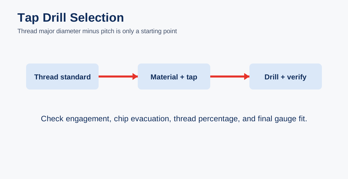
A drill size chart for taps is a starting reference, not a universal answer. Choose the tap drill from the thread standard, nominal diameter, pitch or TPI, material, tap style, desired thread percentage, hole depth, and whether the hole is coated or plated later. For common metric threads, a quick estimate is major diameter minus pitch; for imperial threads, major diameter minus 1 divided by TPI is a useful approximation. Final production holes should be validated with the specified tap, material, gauge, and engagement requirement.
How to Read a Drill Size Chart
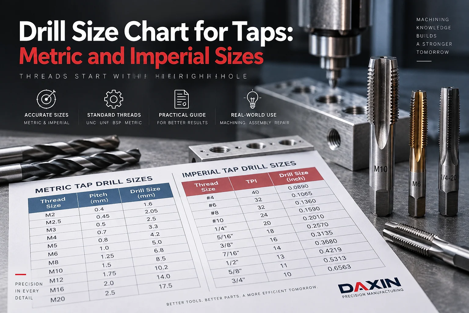
A tap drill chart normally lists the finished thread, pitch or TPI, and the recommended drill diameter. Metric charts use millimeters, while imperial charts may use fractional, numbered, or letter drills. A drill bit size chart may show the same diameter in multiple systems, but the labels are not interchangeable without checking the actual decimal size.
Use the chart to identify a candidate, then confirm the drawing standard and tap class. M6 x 1.0, M6 x 0.75, 1/4-20 UNC, and 1/4-28 UNF all have different thread geometry and different preferred drills. A coarse-thread drill is not automatically suitable for the fine-thread version of the same nominal diameter.
For related process risks, see our guide to common CNC drilling and tapping failures.
Metric Tap Drill Size Chart
| Metric thread | Pitch (mm) | Common starting drill (mm) | Typical use note |
|---|---|---|---|
| M3 x 0.5 | 0.50 | 2.5 | Small hardware and brackets |
| M4 x 0.7 | 0.70 | 3.3 | General machine assemblies |
| M5 x 0.8 | 0.80 | 4.2 | Fixtures, covers, and housings |
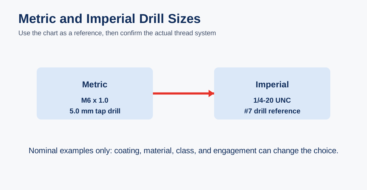
| M6 x 1.0 | 1.00 | 5.0 | Common structural fastener |
| M8 x 1.25 | 1.25 | 6.8 | General-purpose mounting |
| M10 x 1.5 | 1.50 | 8.5 | Frames and larger brackets |
| M12 x 1.75 | 1.75 | 10.2 | Heavy-duty machine hardware |
| M16 x 2.0 | 2.00 | 14.0 | Large structural connections |
These are common nominal references for standard metric coarse threads. A supplier may select a nearby drill to target a specific thread percentage, reduce torque in a difficult alloy, or match a forming tap rather than a cutting tap. Always confirm the tap manufacturer’s recommendation when the thread is critical.
Imperial Tap Drill Size Chart
| Imperial thread | TPI | Common drill reference | Decimal drill size (in) |
|---|---|---|---|
| #4-40 UNC | 40 | #30 | 0.1285 |
| #6-32 UNC | 32 | #36 | 0.1065 |
| #8-32 UNC | 32 | #29 | 0.1360 |
| #10-24 UNC | 24 | #25 | 0.1495 |
| 1/4-20 UNC | 20 | #7 | 0.2010 |
| 5/16-18 UNC | 18 | F | 0.2570 |
| 3/8-16 UNC | 16 | 5/16 in | 0.3125 |
| 1/2-13 UNC | 13 | 27/64 in | 0.4219 |
| 5/8-11 UNC | 11 | 17/32 in | 0.5313 |
| 3/4-10 UNC | 10 | 21/32 in | 0.6563 |
Imperial references above use common UNC values. UNF, UNEF, NPT, BSP, STI, and other thread forms require their own tables. Number and letter drills can vary slightly by chart convention, so use the decimal diameter and the tap supplier’s data when a close fit or controlled thread percentage is required.
Metric and Imperial Reference Diagram
Tap Drill Selection by Tap Type
Cutting taps
Cutting taps remove material from the hole. The selected drill leaves space for the thread profile and the chips. Blind holes need extra depth below the full thread, and the flute style should match material and chip evacuation needs.
Forming or roll taps
Forming taps displace material instead of cutting a chip. They normally require a larger pre-drilled hole than a cutting tap and need ductile material with suitable elongation. Using a cutting-tap drill for a form tap can produce excessive torque, undersized threads, or tap breakage.
Bottoming taps
Bottoming taps finish threads near the bottom of a blind hole but still need a lead tap or adequate chamfer depending on the process. Drill depth, tap chamfer length, and chip space must be checked before the tool enters the hole.
Material and Thread Percentage
Aluminum, brass, mild steel, stainless steel, and plastics respond differently to drilling and tapping. A high thread percentage can improve theoretical stripping strength but also increases torque and the risk of galling or tap breakage. In soft material, an oversized hole may reduce holding strength; in hard or work-hardening alloys, a slightly more forgiving drill can protect tool life and process stability.
Thread percentage should follow the fastener load, engagement length, material strength, and design standard. Do not assume that the smallest chart drill is always the strongest or best production choice. Measure the actual hole, use cutting fluid appropriate to the material, and inspect the finished thread with a calibrated plug gauge or functional mating part.
Blind Holes, Through Holes, and Depth
- For blind holes, drill deeper than the required full thread to allow for point angle, chip space, and tap chamfer.
- For through holes, provide an exit condition that prevents burrs from damaging the mating surface.
- Use a drill point and peck strategy that clears chips without work-hardening the wall.
- Control hole position from functional datums before tapping.
- Specify minimum full-thread depth separately from total hole depth.
Deep small holes are sensitive to runout and chip packing. A rigid setup, spot drill, suitable coolant, and controlled peck cycle are often more important than changing one letter drill size.
Standard Drill Bit Sizes and Measurement
Standard drill bit sizes include metric increments, fractional inches, number drills, and letter drills. The chart label is only useful if the actual diameter is known. Verify worn or reground drills with a micrometer, optical comparator, or calibrated drill gauge. A drill that measures correctly at the shank may have a damaged margin or chipped cutting edge that produces a poor hole.
Hole size after drilling depends on runout, material, point geometry, feed, coolant, machine rigidity, and burr formation. Reaming or boring may be needed when a tapped hole must also locate a dowel, provide a close clearance, or meet a controlled position requirement.
Inspection and Quality Control
Inspect the pilot hole before tapping when the thread is critical. Check diameter, position, depth, perpendicularity, and burrs. After tapping, use a GO/NO-GO plug gauge, thread ring gauge, or approved mating fastener according to the drawing. A gauge confirms functional fit but does not replace checks of location, wall thickness, or thread depth.
First article inspection should record the drill diameter, tap type, cutting data, lubricant, gauge result, and material lot. In batch production, monitor tap wear and torque trends. A worn tap may still produce a thread that starts but fails at full depth or has unacceptable flank damage.
RFQ and Drawing Notes
- State metric, UNC, UNF, BSP, NPT, STI, or another exact thread standard.
- Include nominal size, pitch or TPI, class, handedness, and minimum full-thread depth.
- Specify cutting or forming tap when it affects the pilot-hole size.
- Identify blind or through hole, drill depth, countersink, chamfer, and burr limit.
- Define inspection gauge and whether a functional mating check is required.
- Note coatings or plating that may change internal thread fit.
For a practical thread reference, see our guide to measuring thread size, pitch, TPI, and fit.
Frequently Asked Questions
1. What is a tap drill?
A tap drill is the pilot drill used to create the hole before cutting or forming internal threads.
2. How do I calculate a metric tap drill size?
A quick estimate for a standard metric thread is major diameter minus pitch, such as 6.0 minus 1.0 for approximately 5.0 mm. Confirm the final value with the tap maker and required thread percentage.
3. How do I calculate an imperial tap drill size?
A useful approximation is major diameter minus 1 divided by TPI. Use the exact UNC, UNF, or other thread chart for production work.
4. Is a drill bit size chart the same as a tap drill chart?
No. A drill bit chart lists available diameters; a tap chart recommends a pilot diameter for a particular thread, material, and tap type.
5. What drill size is used for M6 x 1.0?
5.0 mm is a common starting drill for an M6 x 1.0 cutting tap. Material, thread percentage, and forming-tap use may change the recommendation.
6. What drill size is used for 1/4-20 UNC?
#7, approximately 0.2010 inch, is a common reference for a 1/4-20 UNC cutting tap.
7. Do forming taps use the same drill as cutting taps?
No. Forming taps generally require a larger pilot hole because they displace material instead of cutting chips.
8. Why does a tapped hole feel tight?
Possible causes include an undersized or tapered pilot hole, worn or damaged tap, poor lubrication, chip packing, incorrect thread standard, coating buildup, or excessive thread percentage.
9. How deep should I drill a blind tapped hole?
Drill deeper than the required full-thread depth to allow for the drill point, tap chamfer, and chip space. The required margin depends on the tool and hole geometry.
10. How should tapped holes be inspected?
Use the specified GO/NO-GO plug gauge or approved mating fastener, and also inspect location, depth, burrs, and adjacent dimensions when they affect assembly.
Related DAXIN Services
DAXIN supports CNC drilling, tapping, thread milling, reaming, boring, countersinking, thread gauging, CMM inspection, first article reporting, and batch process control.
Final Thoughts
A drill size chart is valuable when it is treated as an engineering reference rather than an automatic answer. Confirm the thread system, tap type, material, depth, thread percentage, and inspection method before releasing the drawing. That discipline produces reliable tapped holes and prevents avoidable broken taps, loose threads, and assembly delays.
Request a Threaded-Hole Review
Send your drawing, thread standard, material, quantity, hole depth, and inspection requirements to DAXIN CNC for a drilling and tapping review.