
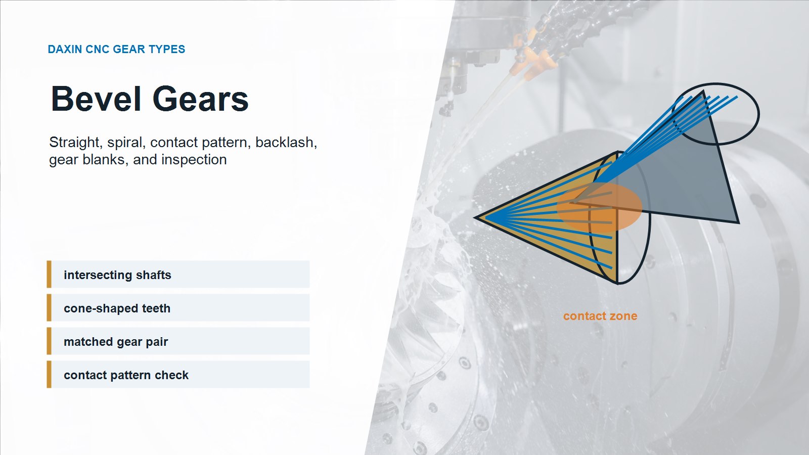
Bevel gears are used when power must turn a corner, usually between shafts that intersect at 90 degrees. Unlike spur gears, bevel gears have cone-shaped tooth geometry, so contact pattern, mounting distance, backlash, bore concentricity, and matched gear inspection are critical. A bevel gear that looks dimensionally acceptable can still run noisy or wear quickly if the gear pair is not controlled correctly.
For CNC machining and gear sourcing, the main question is not only whether the part can be cut. The real question is whether the gear blank, bore, cone geometry, tooth form, heat treatment, and final contact pattern are controlled as a working pair.
Key Takeaways
- Bevel gears transfer motion between intersecting shafts. A 90-degree shaft angle is common, but other angles are possible.
- Straight bevel gears are simpler. They are often used at lower speeds or where cost and simplicity matter.
- Spiral bevel gears are smoother and quieter. They are better for higher speed or more demanding applications, but they require more precise manufacturing.
- Backlash and contact pattern matter. Too much backlash creates lost motion; too little can cause heat, binding, and noise.
- Inspection should treat bevel gears as a pair. Bore fit, runout, mounting distance, tooth contact, and FAI are all important.
What Are Bevel Gears?
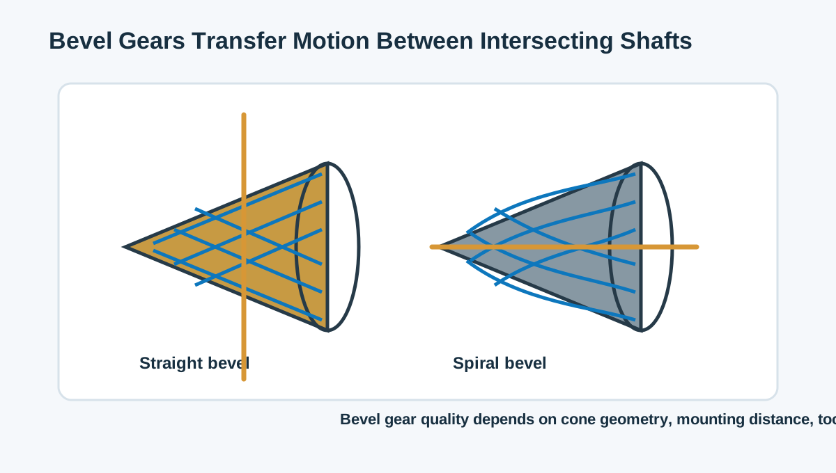
Bevel gears are gears with teeth formed on a cone-like surface. They are used to transmit rotation between shafts that intersect. The most common arrangement is a right-angle drive, where one shaft turns another shaft at 90 degrees. Bevel gears are found in gearboxes, hand tools, differential mechanisms, rotary drives, industrial equipment, automation systems, and compact mechanical assemblies.
Because the teeth are formed on a cone, bevel gear geometry is more complex than a flat spur gear. The tooth size changes across the face width, and the gear must be mounted at the correct distance and angle to mesh properly.
Straight Bevel Gears vs Spiral Bevel Gears
The two common types are straight bevel gears and spiral bevel gears. Straight bevel gears have teeth that run straight toward the cone apex. They are simpler and can be suitable for lower-speed applications. Spiral bevel gears have curved teeth that engage more gradually, which helps reduce noise and improve smoothness.
| Gear Type | Main Advantage | Manufacturing Concern | Typical Use |
|---|---|---|---|
| Straight bevel gear | Simple geometry and lower manufacturing cost | More noise and impact at higher speeds | Manual drives, low-speed mechanisms, simple gearboxes |
| Spiral bevel gear | Smoother engagement and lower noise | More complex tooth cutting and paired inspection | Higher-speed reducers, automotive-style mechanisms, precision drives |
The best choice depends on speed, load, noise requirement, cost, gear size, and inspection level. For many industrial mechanisms, straight bevel gears may be enough. For smoother motion and better high-speed behavior, spiral bevel gears are often preferred.
Why Contact Pattern Matters
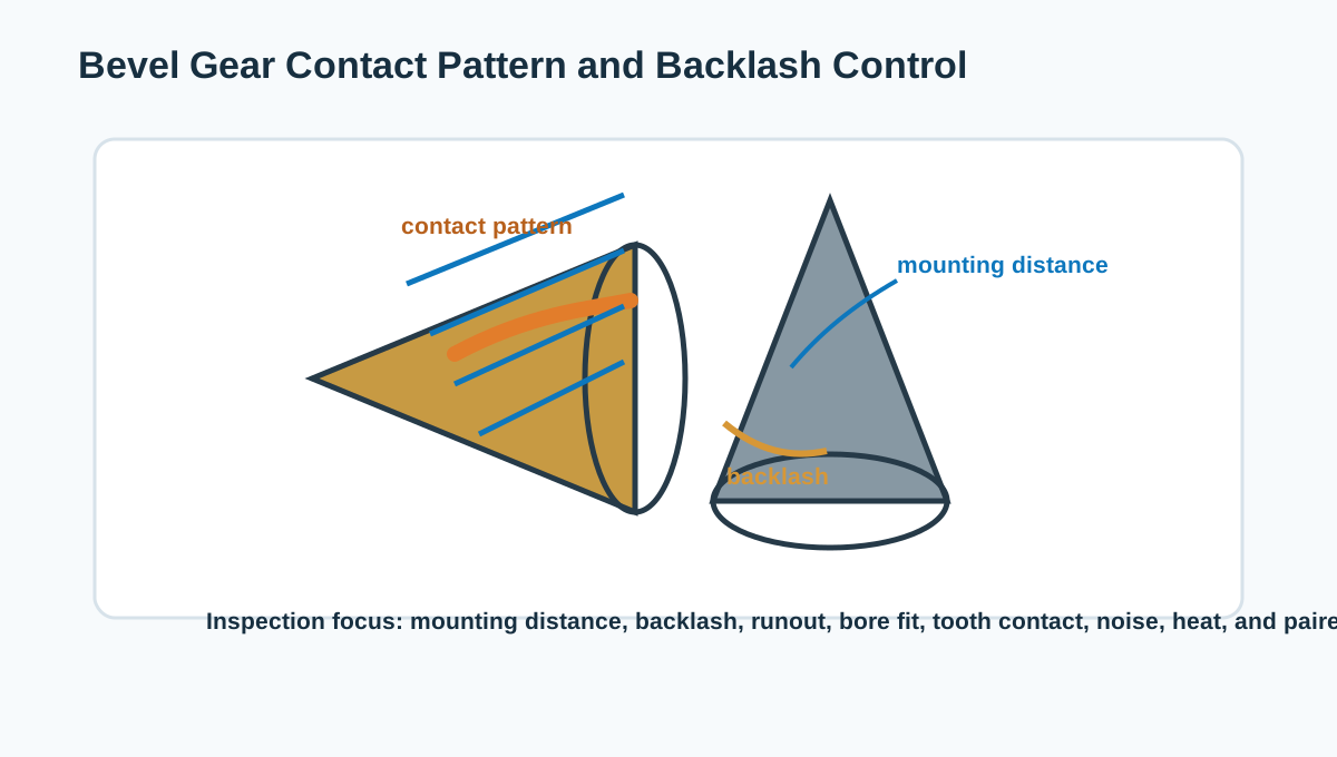
The contact pattern shows where the teeth actually touch when the bevel gear pair is assembled. It is one of the most important checks because bevel gears are sensitive to mounting distance, shaft angle, bore accuracy, face runout, and tooth form. If the contact is too close to the toe, heel, root, or edge, the gear can become noisy or wear unevenly.
Contact pattern inspection usually uses marking compound or dedicated gear inspection equipment. For precision gear sets, the pattern should be checked under controlled assembly conditions. This is why bevel gears are often treated as matched pairs rather than completely independent parts.
Backlash in Bevel Gears
Backlash is the clearance between mating teeth. In bevel gears, backlash affects motion accuracy, noise, heat, and durability. If backlash is too large, the mechanism may have lost motion or impact noise when reversing direction. If backlash is too small, the gear set may bind, overheat, or wear quickly.
The correct backlash depends on gear size, material, speed, load, lubrication, operating temperature, and application. For positioning mechanisms, backlash may need tighter control. For heavy-duty drives, enough clearance may be required to allow lubrication and thermal expansion.
CNC Machining the Bevel Gear Blank
Before tooth cutting, the bevel gear blank must be machined accurately. The bore, mounting face, cone blank, hub, keyway, bolt holes, and datum surfaces affect tooth cutting and final assembly. If the blank bore is not concentric or the face has excessive runout, the gear may not cut or run correctly.
For bevel gear blanks, CNC turning and milling often prepare the geometry before specialized gear cutting. Bore gauge inspection is useful for the center bore. CMM inspection can verify datum relationships, bolt patterns, keyways, and mounting surfaces. Micrometer inspection can check hub thickness, OD, shoulders, and face width.
Materials for Bevel Gears
Material choice depends on load, wear, noise, corrosion, heat treatment, and cost. Steel and alloy steel are common for load-bearing bevel gears. Stainless steel may be used when corrosion resistance matters, though machining and tooth finishing can cost more. Brass, bronze, and engineering plastics may be used for light-load or low-noise applications.
- Alloy steel is common when strength, wear resistance, and heat treatment are required.
- Carbon steel can be practical for moderate load and cost-sensitive applications.
- Stainless steel is useful in corrosive environments but requires careful machining and finishing.
- Bronze or brass may be selected for certain wear, corrosion, or low-friction needs.
- Engineering plastics can reduce weight and noise for low-load mechanisms.
Heat Treatment and Distortion
Bevel gears often need heat treatment for strength and wear resistance. Carburizing, induction hardening, nitriding, or through hardening may be used depending on material and application. Heat treatment can change bore size, runout, tooth geometry, and contact pattern.
For precision bevel gears, the process may include rough machining, heat treatment, finish machining or grinding, and final contact pattern inspection. If the gear is heat treated after tooth cutting, distortion allowance and final correction should be planned. If the bore or mounting face is critical, final grinding or honing may be required after heat treatment.
Inspection for Bevel Gear Quality
Bevel gear inspection should combine component inspection and pair inspection. Individual part dimensions matter, but the gear pair’s function matters more. A good inspection plan checks both the machined blank and the final meshing behavior.
- CMM inspection for datums, mounting faces, bolt holes, keyways, and gear blank geometry.
- Bore gauge inspection for shaft fits, bearing fits, and center bores.
- Micrometer inspection for OD, hub diameter, thickness, and shoulders.
- Runout inspection for bore, face, cone blank, and gear mounting features.
- Contact pattern inspection for actual tooth meshing location.
- Backlash measurement for assembly clearance and motion accuracy.
- Surface roughness inspection for tooth surfaces, bearing seats, and mating faces.
- FAI before batch production to confirm machining, heat treatment, tooth cutting, and inspection.
Common Problems in Bevel Gear Projects
- Poor contact pattern caused by wrong mounting distance, runout, bore error, or tooth geometry error.
- Excessive backlash leading to lost motion, impact, and noise.
- Too little backlash causing heat, binding, wear, or assembly difficulty.
- Blank runout that affects tooth cutting and final mesh quality.
- Heat treatment distortion that changes bore size, face runout, or tooth contact.
- Unclear paired gear requirements that make inspection and replacement difficult.
Design Tips for Bevel Gear Parts
- Define whether the gear is straight bevel, spiral bevel, or another bevel type.
- Specify shaft angle, mounting distance, bore fit, and datum scheme clearly.
- Control the gear blank before tooth cutting: bore, face runout, hub, OD, and keyway.
- Define backlash range and contact pattern acceptance when performance matters.
- Plan heat treatment and final finishing before production starts.
- Consider paired inspection for bevel gear sets instead of only individual dimensions.
- Use FAI for first parts before releasing batch production.
Related CNC Machining Resources
Bevel gears connect closely with gear blanks, tooth contact, backlash, and shaft alignment. You may also want to read our guides on CNC machined gear blanks, worm gears in CNC machining, gear accuracy and quality control, and DAXIN’s CNC machining services.
FAQ
What are bevel gears used for?
Bevel gears are used to transfer motion between intersecting shafts, commonly at 90 degrees. They are found in gearboxes, drives, tools, rotary mechanisms, and compact mechanical systems.
What is the difference between straight bevel and spiral bevel gears?
Straight bevel gears have straight teeth and simpler manufacturing. Spiral bevel gears have curved teeth, smoother engagement, and lower noise, but require more precise manufacturing and inspection.
Why is contact pattern important for bevel gears?
The contact pattern shows where the teeth actually touch. A poor pattern can cause noise, uneven wear, heat, and reduced gear life even if basic dimensions look acceptable.
Should bevel gears be inspected as a pair?
Often, yes. Bevel gear performance depends on how the two gears mesh together, so backlash and contact pattern inspection are important for many applications.
Final Thoughts
Bevel gears are more than cone-shaped gears. They are matched mechanical components where blank accuracy, tooth geometry, mounting distance, backlash, contact pattern, material, heat treatment, and inspection all work together. When these details are controlled from CNC blank machining through final gear inspection, bevel gears can deliver smooth and reliable right-angle power transmission.